
This chapter explains how to use the IP Security feature and contains the following sections:
This section provides an overview of IP security capabilities for both IPv4 and IPv6.
To protect IP packets sent to another host, router, or firewall, you may configure a secure tunnel for each IP route that must be secure. An IPSec tunnel is a two-way logical connection to the remote host, router, or firewall over which a local router sends protected IP packets. A secure tunnel is identified by parameters such as the addresses of the source host and destination host, port numbers, and tunnel ID.
With IPv4 you can define a negotiated tunnel by configuring a tunnel policy in the policy database, or you can create a manual tunnel using the Talk 6 add tunnel command as shown at Configuring the Tunnel for Router A. With IPv6, use the Talk 6 add tunnel command.
To establish a secure IPSec tunnel, a policy may specify the IP Authentication Header (AH) function (see IP Authentication Header), which attaches special authentication headers, and the IP Encapsulation Security Payload (ESP) function (see IP Encapsulating Security Payload), which encrypts the data. The policy establishes which of the following security measures are implemented for packets:
| Note: | For each secure tunnel, the sender and the receiver must select identical options. |
Packets sent using the Internet Protocol (IP) can be made secure by using the IP Security feature of the 2212.
Security, as defined by RFC 2401 - Security Architecture for the Internet Protocol, consists of the following functions:
| Note: | In some countries, encryption support is not provided because of U.S. export regulations, and the encryption parameters are not displayed. However, the ESP-NULL algorithm is always available. For a definition of the ESP-NULL algorithm, see ESP Encryption Algorithms. |
The following terms are used when describing IPSec topics related to IPv4:
| Note: | You should check with the CA on a regular basis to ensure that you are using a current list of ISAKMP-enabled parties. See the PKI Talk 6 load command at Public Key Infrastructure Configuration Commands for details. |
The Authentication Header (AH) is described in RFC 2402 IP Authentication Header. This header contains authentication data for the IP datagram.
For IPv4 using negotiated IPSec, the policy assigned to a datagram implements a cryptographic authentication function that relies upon the Internet Key Exchange (IKE) protocol and a public/private key pair. For IPv4 manual tunnels and for IPv6, the sender uses a cryptographic function that relies upon a secret authentication key. In either case, the cryptographic authentication function is applied to the contents of the datagram. You may specify AH alone or with ESP. See Using AH and ESP for details.
A secure tunnel that uses the AH tunnel policy must use one of the following authentication algorithms:
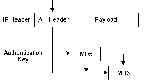
These AH algorithms combine a keyed message authentication function using cryptographic hashing (hashed message authentication code, abbreviated as HMAC) with an optional replay prevention function. Replay prevention uses a sequence number contained in the AH to verify that a packet has not been received previously. Replay prevention protects the receiver from denial-of-service attacks, in which the same packet is sent repeatedly and the router becomes so busy processing the duplicate packets that it cannot process legitimate traffic. An authentication code is applied to a secret cryptographic key and the data, then to the output of the secret key and the output of the first operation. See Figure 33 for an illustration of how this is done for HMAC-MD5.
Figure 33. Creation of an HMAC MD5-Authenticated Message

IP Encapsulating Security Payload (ESP) is described in RFC 2406 IP Encapsulating Security Payload. ESP encrypts part or all of the IP packet to provide confidentiality in addition to authentication (optional) and integrity. However, if you select the ESP-NULL algorithm, ESP performs only authentication and integrity checking. You may specify ESP alone or with AH. See Using AH and ESP for details.
The algorithms available for ESP authentication are the same as those for AH, previously shown at AH Authentication Algorithms.
A secure tunnel that uses the ESP encryption policy must either use one of the following encryption algorithms or the ESP-NULL algorithm:
| Note: | Except for ESP-NULL, the ESP encryption algorithms are subject to U.S. export laws. If your 2212 does not allow you to use some or all of these algorithms, sale of those algorithms may be prohibited in your country. Check with your IBM representative for more information. |
The ESP-NULL algorithm does not encrypt the cleartext data and is available in all countries. It enables ESP authentication and integrity checking only, not encryption. If you use ESP-NULL, you must use one of the ESP authentication algorithms.
A secure tunnel may use one of the following authentication/encryption selections: AH, ESP, AH-ESP, or ESP-AH. If you want a combination of AH and ESP, the following statements apply:
A Security Association (SA) is a simplex "connection" that affords security services to the traffic carried by it. Security services are afforded to an SA by the use of AH or ESP, but not both. If both AH and ESP protection are applied to a traffic stream, then two (or more) SAs are created to afford protection to the traffic stream. To secure typical bidirectional communication between two hosts or between two security gateways, two SAs (one in each direction) are required.
The operational mode (either tunnel or transport) determines how IPSec handles IP packets. Tunnel mode is the default, and is required if the router is acting as a security gateway. It protects data on a single segment of a path through a network. Transport mode is allowed only when the router is acting as a host, and protects data end-to-end, along a complete path.
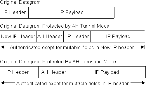
In tunnel mode, the AH is placed in front of the IP packet and a new IP header is created and placed in front of the AH. The IP header of the packet being tunnelled (inner header) carries the ultimate source and destination addresses of the packet. The new IP header (outer header) can contain the addresses of security gateways, which are the tunnel endpoints. The AH protects the entire new packet, both the new IP header and the IP packet being tunnelled, except for the mutable fields in the new IP header.
In transport mode, the AH is inserted after the IP header and before the header of an upper-layer protocol, such as TCP or UDP. In this mode, AH authenticates the upper-layer protocol header and the contents of the IP packet, except for the mutable fields in the IP header (such as time-to-live [TTL], checksum, fragment flag, fragment offset, and type of service [TOS]).
Figure 34 shows the format of AH-protected datagrams.
Figure 34. AH-Protected Datagram Format
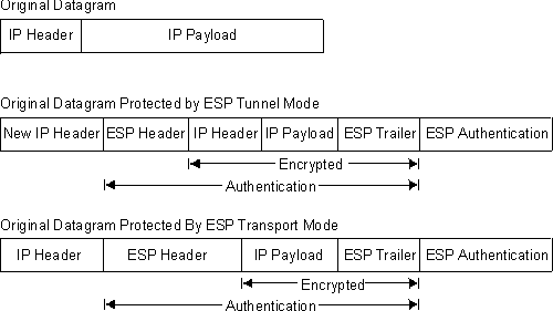
In tunnel mode, the payload data contains the entire IP packet, and a new IP header is created and placed in front of the ESP header. The IP header of the packet being tunnelled (inner header) contains the ultimate source and destination addresses of the packet, while the new IP header (outer header) contains the addresses of security gateways. ESP encrypts the tunnelled IP packet. If you use ESP authentication, the ESP header, the tunnelled IP packet, and the ESP trailer are authenticated.
In transport mode, the payload data contains encrypted upper-layer protocol data, such as TCP or UDP data. If you use authentication, the ESP header, the upper-layer protocol data, and the ESP trailer are authenticated.
Figure 35 shows the format of ESP-protected datagrams.
Figure 35. ESP-Protected Datagram Format
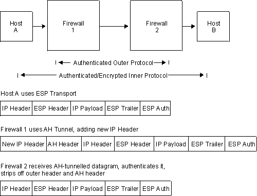
You may nest one protocol within another instance of itself or the other protocol. Figure 36 shows the effects of nesting an ESP-protected datagram within an AH tunnel.
Figure 36. Nesting ESP Within an AH Tunnel
With IPv4, you may also use IPSec to protect L2TP packets. After creating an L2TP tunnel by encapsulating an L2TP frame inside a UDP packet, you may encapsulate the UDP packet inside an IP packet whose source and destination addresses define the tunnel's end points. Then you can apply AH, ESP, and ISAKMP protocols to the IP packet. Figure 37 shows an IP-encapsulated L2TP packet including PPP and its payload protocol for transmission across the Internet.
Figure 37. IPSec-Protected L2TP Packet

For greater security, in addition to the security features already discussed, you may encapsulate the packets of a traffic stream twice and transmit them first through one IPSec tunnel and then through another (tunnel-in-tunnel).
| Note: | The use of multiple encryption (using tunnel-in-tunnel mode when encryption is preformed for both tunnels) within the router is restricted by U.S.A. Government export regulations. It is only supported in software loads that are under strict export control (software loads that support RC4 with 128 bit keys and Triple DES). |
With IPv4, a rule in the policy database designates a packet for encapsulation (inner) for the first tunnel, and before the packet is sent, the rule causes the packet to be submitted to a second tunnel for a second encapsulation (outer). With IPv6, a packet filter access control rule identifies a packet for encapsulation (inner) for the first tunnel, and before the packet is sent, a second rule causes the packet to be submitted to a second tunnel for a second encapsulation (outer).
The two IPSec tunnels originate in the same router and the remote ends of the tunnels are at the same physical location, but on different machines. The remote end of the first tunnel can be either a secure gateway or a host; the remote end of the second tunnel must be a secure gateway router. Because the tunnels have different destinations, they must have different remote IP addresses. Both tunnels used for tunnel-in-tunnel must be configured for tunnel mode, and extra padding is not allowed on the second tunnel.
After it has been encapsulated twice, the packet is transmitted through the second (outer) tunnel. At the end of that tunnel, the outer encapsulation is removed and the packet is forwarded to the first tunnel (inner), based on information in the header created by the first tunnel encapsulation. At the end of this tunnel, the inner encapsulation is removed and the packet is forwarded to its final destination.
For both IPv4 and IPv6, IPSec supports Path Maximum Transmission Unit (PMTU) Discovery if the 2212 is acting as a security gateway. Support of PMTU Discovery is a concern if a packet cannot be fragmented. With IPv4, a packet cannot be fragmented if the Don't Fragment (DF) bit is set. With IPv6, a packet cannot be fragmented by intermediate routers. In these situations, if the packet does not fit on a link in the path from one end of the secure tunnel to the other, a "packet too big" ICMP error message is sent to the packet originator.
Because the router is acting as a security gateway, the error packet is returned to the originating router instead of the true originator of the packet. The receiving router must pass the reported MTU back to the true originator, who can reduce the packet size so that it will reach the final destination. Support for PMTU Discovery is discussed in RFC 2401 - Security Architecture for the Internet Protocol.
IPv4 provides the following options for the DF bit setting in the outer header of the tunnelled packet:
In these circumstances, for IPv4, the DF bit is not set, regardless of the configuration, and the secure packet may be fragmented as needed on the path to the receiver. For IPv6, the packet is fragmented as needed as it leaves the security gateway so that it fits on the PMTU for the tunnel. This special action is needed because the incoming packet is already less than or equal to the minimum MTU, so the originating host will not decrease the size any further. If fragmentation were not allowed, this packet would never reach its final destination
Because changes in the network topology or configuration can change the PMTU, the PMTU value must be aged out periodically and reset to the maximum. The aging timer value defaults to 10 minutes and can be configured with the Talk 6 set path command. Setting the aging parameter to 0 disables PMTU aging.
Figure 38 shows an example of a network with two IPSec tunnels that connect router A (with IPSec) to router B (with both IPSec and Network Address Translation for IPv4).
Figure 38. Network with IPSec and NAT
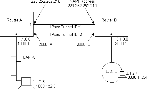
In this network, an IPSec tunnel with IPSec tunnel ID 1 has been configured from IPv4 address 223.252.252.216 in router A to IPv4 address 223.252.252.210 in router B. Router A is configured for IPSec. Router B is configured for both IPSec and NAT.
Also in this network, an IPSec tunnel with IPSec tunnel ID 2 has been configured from IPv6 address 2000::A in Router A to IPv6 address 2000::B in Router B.
With IPv4, to configure this network for IKE, follow the steps starting at "Configuring Internet Key Exchange (IPv4)". For IPv4 with manual IPSec, follow the steps starting at "Configuring a Manual Tunnel (IPv4)". For IPv6, follow the steps starting at "Configuring a Manual Tunnel (IPv6)".
| Note: | Even if you do not plan to use NAT in your network, the description of configuring router B can help you understand the relationships between the parameters at each end of the IPSec tunnel more clearly. |
This section explains how you can use the Internet Key Exchange (IKE) to automate the definition and creation of IPSec security associations (SAs). IKE is a standard supported by the IETF (RFC 2409), which provides a standard way for IPSec-enabled products from the same or different vendors to communicate about their security requirements.
IKE provides a framework by means of which the following security requirements are met:
IKE defines two distinct negotiation exchanges: Phase 1 and Phase 2. Phase 1 sets up a secure tunnel between the two IKE peers, which will provide protection for the subsequent IPSec tunnel negotiations. The following actions occur during Phase 1 in the order shown:
In pre-shared key mode, both IKE peers, by means of a previous off-line process, have exchanged a key, and this is used during Phase 1 to authenticate the peer. You configure the pre-shared key using the policy feature's add user command.
In signature mode, a signed X.509 digital certificate is used to provide keys that are used to encrypt and decrypt the payloads of Phase 1 messages.Successful signing and verifying comprises authentication of the peer. For a detailed discussion of signature mode and the use of X.509 digital certificates, see Using Public Key Infrastructure.
Phase 1 negotiations can take place using either of two exchange modes:
The processing discussed in this topic occurs when a router prepares to send a packet whose attributes match those defined in a rule in a policy database. Negotiating a tunnel occurs in two phases. During Phase 1, the sending router initiates communication by transmitting the first message of a six-message exchange, which establishes the security options to be used during Phase 2. The receiver responds and the two parties negotiate the ISAKMP security association (SA) characteristics, the authentication and encryption algorithms to be used, and they authenticate each other's identity. During Phase 2, the parties exchange a total of three messages to negotiate the SAs and keys to be used to protect IP datagrams sent between the two. Phase 1 proceeds as follows:
At this point, both parties have authenticated themselves to the other, agreed on the characteristics of the SA, and have derived keys and key-related information for handling ISAKMP SAs. Now the parties enter Phase 2 to negotiate the non ISAKMP SAs and keys, which will be used to protect IP datagrams exchanged between them. Phase 2 proceeds as follows:
This section explains how to use the public key infrastructure (PKI). Through PKI, IKE supports public key signature mode for authenticating IKE entities. Although this release supports pre-shared key mode, which does not require PKI support, this mode contains an inherent disadvantage. For authentication, it requires that you configure each IKE entity with the pre-shared key of each of its peers. This severely limits the scalability of IKE operations. Public key-based signature or public encryption mode provides much better scalability. In this release, the X.509 digital certificate is used in signature mode IKE Phase 1 negotiations to authenticate IKE entities.
You assign an identity to each IKE entity that you want to participate in IKE negotiations by specifying a unique value in the ISAKMP ID field when you configure its user policy profile. Each IKE entity authenticates its identity with its peers.
PKI is currently being defined and developed to support public key operation. In PKI, an X.509 digital certificate binds an entity's public key to its claimed identity. An IKE entity can extract the public key contained in a certificate. It can then perform a public key operation to authenticate the identity of a peer that is participating in an IKE negotiation. A public key is used for IKE signature mode. In this mode, the signer uses its private key to sign the digital signature. The receiver extracts the signer's public key from the certificate and uses it to verify the signature. The digital certificate function provides a scalable way for one IKE entity to authenticate the identity of another IKE entity.
This release assumes that both IKE entities in a negotiation use the same CA. Before starting IKE negotiations using the signature, you must configure PKI for the router. You must also generate the router private key and router certificate, and have downloaded the root CA's certificate. The following steps explain how to configure PKI:
Because public key operation involves a key pair (signature mode uses the private key to sign and the public key to verify), you must generate a key pair for the router. For a certificate request, you must send the generated public key to the CA to be put into an X.509 digital certificate. Then every potential IKE peer can extract this public key from the CA-issued certificate. The private key resides in the router and is kept secret, known only to the router.
In this version, you may issue a certificate request command, which does the following:
The CA receives the PKCS#10 certificate request. The CA may manually verify the request and issue a certificate. The certificate contains the router public key and the information that you entered. The CA signs the certificate using its private key, thus it becomes trusted digital information as long as you trust the signing CA. The certificate is now ready to be used in IKE negotiations. (This processing is outside the scope of the router operation and is not discussed in further detail in this book.)
Once the CA has issued the certificate, PKI can download it into the router. Depending on how the CA publishes the certificate, PKI can use either TFTP or LDAP to do the download.
Note that the private key and the public key in the router certificate must match in order to perform public key operation such as digital signature. When PKI downloads the certificate into the router, the private key that was generated with the public key must be in the router key cache. The downloaded certificate is useless if it loses its matching private key. This means that from the time you issue the certificate request to the time the certificate downloads, you must not restart or reload the router, clear cache, or issue a new certificate request. Any of these operations destroy the private key in the router running cache.
To verify the IKE peer's certificate, PKI must obtain the peer's root CA certificate. This release supports single level CA operation, which means that the IKE entities must be assigned to the same CA. Each IKE entity (in this case, each router) must download the CA's certificate (using either TFPT or LDAP) to verify that the certificate received from the peer is valid.
After the router has obtained the certificate, its matching private key, and the CA's certificate, you can start IKE negotiation. Since a certificate is typically valid for months or years, you may want to save the certificate and the private key in SRAM so that you do not have to issue a certificate request and do a download each time you reload or restart the router. This version provides the cert save and cert load commands to save or retrieve the certificate and private key in SRAM.
Note that the router certificate and private key must be processed as a pair (for example, they are always saved or retrieved from SRAM together).
Use Talk 6 commands to configure and list both TFTP and LDAP server information as shown in the following examples:
Config>f ipsec
IP Security feature user configuration
IPsec config>pki
PKI config>add server
Name ? (max 65 chars) []? test
Enter server IP Address []? 8.8.8.8
Transport type (Choices: TFTP/LDAP)  [TFTP]?
PKI config>
PKI config>li server

1)  Name: SERVER1
    Type: TFTP
    IP addr: 8.8.8.8


2)  Name: TEST
    Type: TFTP
    IP addr: 8.8.8.8
PKI config>li cert

Root CA  certificate:
       SRAM    Name:   R1
       Subject Name:   /c=US/o=ibm/ou=nhd
       Issuer  Name:   /c=US/o=ibm/ou=nhd
           Validity:   1998/12/19 -- 2018/12/19
  Default Root Cert:   No

       SRAM    Name:   R2
       Subject Name:   /c=US/o=ibm/ou=nhd
       Issuer  Name:   /c=US/o=ibm/ou=nhd
           Validity:   1998/12/19 -- 2018/12/19
  Default Root Cert:   Yes


Router   Certificate:
       SRAM    Name:   B1
       Subject Name:   /c=CA/o=Entrust Technologies/ou=PartnerCA/cn=ibm3
       Issuer  Name:   /c=CA/o=Entrust Technologies/ou=PartnerCA
   Subject alt Name:   1.1.1.1
         Key Usuage:   Sign & Encipherment
           Validity:   1998/10/29 -- 2001/10/29
       Default Cert:   No

       SRAM    Name:   B2
       Subject Name:   /c=CA/o=Entrust Technologies/ou=PartnerCA/cn=ibm3
       Issuer  Name:   /c=CA/o=Entrust Technologies/ou=PartnerCA
   Subject alt Name:   1.1.1.1
         Key Usuage:   Sign & Encipherment
           Validity:   1998/10/29 -- 2001/10/29
       Default Cert:   Yes

       SRAM    Name:   B3
       Subject Name:   /c=CA/o=Entrust Technologies/ou=PartnerCA/cn=ibm3
       Issuer  Name:   /c=CA/o=Entrust Technologies/ou=PartnerCA
   Subject alt Name:   1.1.1.1
         Key Usuage:   Sign & Encipherment
           Validity:   1998/10/29 -- 2001/10/29
       Default Cert:   No

       SRAM    Name:   YYY
       Subject Name:   /c=CA/o=Entrust Technologies/ou=PartnerCA/cn=ibm3
       Issuer  Name:   /c=CA/o=Entrust Technologies/ou=PartnerCA
   Subject alt Name:   1.1.1.1
         Key Usuage:   Sign & Encipherment
           Validity:   1998/10/29 -- 2001/10/29
       Default Cert:   No
PKI Console>cert-req
Enter the following part for the subject name
   Country Name(Max 16 characters) []? us
   Organization Name(Max 32 characters) []? IBM
   Organization Unit Name(Max 32 characters) []? NHD
   Common Name(Max 32 characters) []? router1
Key modulus size
 [512]?
Certificate subject-alt-name type:
   1--IPv4 Address
   2--User FQDN
   3--FQDN
Select choice [1]?
Enter an IPv4 addr) []? 12.1.1.1
Generating a key pair. This may take some time. Please wait ...
PKCS10 message successfully generated
Enter tftp server IP Address []? 8.8.8.8
Remote file name (max 63 chars) [/tmp/tftp_pkcs10_file]?
Memory transfer starting.
.Memory transfer completed - successfully.
Certificate request TFTP to remote host successfully.
Private Key Alias [ROUTER_KEY]? local
Generated private key LOCAL stored into cache
PKI Console>li cert
Router   certificate
      Serial Number:   909343811
      Subject  Name:   /c=CA/o=Entrust Technologies/ou=PartnerCA/cn=ibm3
      Issuer   Name:   /c=CA/o=Entrust Technologies/ou=PartnerCA
   Subject alt Name:   1.1.1.1
         Key Usuage:   Sign & Encipherment
           Validity:   1998/10/29 -- 2001/10/29

Root CA  certificate
      Serial Number:   914034740
      Subject  Name:   /c=US/o=ibm/ou=nhd
      Issuer   Name:   /c=US/o=ibm/ou=nhd
           Validity:   1998/12/19 -- 2018/12/19
PKI Console>cert-save
Enter type of certificate to be stored into SRAM:
     1)Root certificate;
     2)Box  certificate with private key;
Select the certificate type (1-2) [2]?
SRAM Name for certificate and private key []? yyy
Load as default router certificate at initialization?? [No]:
Private key YYY written into SRAM
Both Certificate and private key saved into SRAM successfully
PKI Console>
PKI Console>cert-load
Enter type of certificate to be stored into SRAM:
     1)Root certificate;
     2)Box  certificate with private key;
Select the certificate type (1-2) [2]?
Name []? yyy
Box certificate and private key saved into cache successfully
PKI Console>
The IP security feature contained in IPv4 for the 2212, in conjunction with the policy feature and other IPSec-related processes, provides authentication, integrity, confidentiality, and non-repudiation. To implement IPSec manually, you preconfigure a policy containing a subset of IPSec options in a policy database to define the manual tunnel's profile and validity period. You may also preconfigure the full set of IPSec options (policy) in the database so that when a policy-enabled router prepares to send an IPSec packet, it dynamically negotiates and establishes IPSec options with the destination router, based on the policy's contents. To define a manual tunnel, see "Configuring Manual IP Security (IPv4)". For an explanation of the policy options, see "Using the Policy Feature".
The IP security feature contained in IPv6 for the 2212 provides authentication, integrity, and confidentiality. To define a manual tunnel, see "Configuring Manual IP Security (IPv6)".